iPhone 6S Plus after water front camera normal while rear camera abnormal
It has no backlight after dropping into water.The backlight is fixed, but front camera is normal while the rear camera is not. The 2.8V chip is replaced.
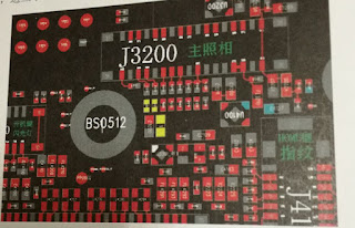
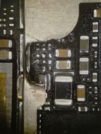
Under the repair rules the simple first and the complicated later, tear down iPhone and replace the rear camera subassembly. When we are going to replace it, we are surprised to find that some components near the camera socket J3200 are eroded. After checking the circuit diagram, we find that three inductors are missing. The three inductors in bitmap are shown in yellow points in picture 6-50.
Picture 6-50
Their material objects are shown in picture 6-51.
Picture 6-51
In real repair cases, we directly short connect the two ends of the inductor to speed up. After the whole iPhone is fixed, we find other workable inductor to assemble. After short connecting the two ends of the inductor, measure the diode data to ground of its socket. The data is normal. We think it recovers now. So we assemble camera and energize it to test. The problem is still the same. Remove the camera and energize motherboard to measure its voltage. First, we measure whether I2C bus has 1.8V voltage as well as the 1.8V and 1.2V voltage that rear camera need. The teat points are shown in yellow parts in picture 6-52.
Picture 6-52
The above voltages are normal. We measure a special voltage 2.85V, the pin 16 in picture 6-53. After assembling rear camera and turn on iPhone to open rear camera, this voltage will appear. We cannot measure it because the flex cable is connected, so we doing jump wire to measure it.
Picture 6-53
After measuring, we find no 2.85V voltage. We have to remind you that the front and rear cameras of iPhone 6 and iPhone 6 Plus use the same 2.85V voltage. If 2.85V voltage has problems, both front and rear cameras cannot be used. The later series of iPhone 6S, the front 2.85V voltage is output by power chip while the rear 2.85V voltage is made by LDO reduction voltage chip U3200. The circuits of LDO chip are shown in picture 6-54.
Picture 6-54
The U3200 in bitmap is shown in picture 6-55.
Picture 6-55
Their material objects of U3200 is shown in picture 6-56 (It is not the original faulty material objects of U3200)
Picture 6-56
Picture 6-57
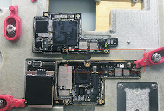
Measure the working condition of VIN and EN, which are normal. Besides, other maintenance has replaced U3200 and I do not have such a chip to replace in my accessories pad. Thus, I remove the U3200 directly and jump a wire from the 3V power supply of NAND Flash. Use the 3V to act as 2.85V. In this way, we can know whether the chip is damaged. The test points of 3V power supply of NAND Flash in bitmap are shown as yellow points in picture 6-58.
Picture 6-58
Connect motherboard to DC power supply and turn it on to test the front and rear camera. When I open camera to test, problems disappear. As I do not have such a chip to replace in my accessories pad, the jump wire is placed like that. I have tested many times and they are normal. If you have a U3200 to replace the damaged one, then replace it rather than jump a wire.


Comments
Post a Comment