iPhone 6 Plus front camera is unworkable
When you ipone 6 Plus has no sound,We have some experience and methods to share,such as Customer sent an iPhone 6 Plus motherboard. He said his iPhone has dropped into water, so the front camera is unworkable and receiver has no sound as well as the screen does not turn black during calls (cannot sense distance).
Repair Process
Assemble the board to tester assembly and test, finding the front and rear cameras are unworkable, receiver has no sound, the screen does not turn black during calls and sound cannot be recorded.
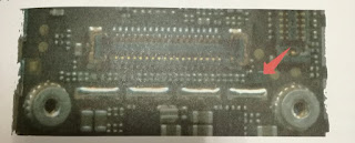
Observing motherboard, we find that the touch assembly is fixed and there are jump wires. We doubt that the high temperature may cause the above problems. Starting from front camera socket J1111, we can see that the socket is split and the light-sense control tube Q1101 has been torn down. Replace the front camera socket and solder light-sense control tube Q1101. The material object of light-sense control tube Q1101 is shown in picture 4-81.
Picture 4-81
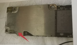
Measure the diode data to ground of pin 1, 2 of front camera socket J1111 (picture 4-82) and the data is infinite. The two pins are receiver signal. Replace the audio chip. The material object of audio chip is shown in picture 4-83.
Picture 4-82

Picture 4-83

After replacing the audio chip, measure the diode data again and data now is normal. We continue to measure the diode data to ground of front camera socket J1111, finding that pin 7 camera 2.85V’s data is higher than normal one. It maybe caused by empty solder of the 2.85V transmission tube. Then we remount the U2301 chip, and measure the diode data to ground of J1111 pin 7. Now the data is normal. The material object of U2301 is shown in picture 4-84.
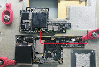
Assemble the board and test the front camera and receiver, which are normal now. There leaves an unsettled problem-the screen does not turn black during calls. Measure the diode data to ground of J1111, which is normal. Measure the power supply of J1111’s pin 23 proximity sensor which is 3.3V and it is normal. Measure the power supply of open signal circuit of J1111’s pin 25 proximity sensor, which is 1.8V and it is lower that normal one. Check the bitmap and find that the opening signal is connected to pin C2 of main touch screen chip U2401, as shown in picture 4-85.
Picture 4-84

Repair Process
Assemble the board to tester assembly and test, finding the front and rear cameras are unworkable, receiver has no sound, the screen does not turn black during calls and sound cannot be recorded.
Observing motherboard, we find that the touch assembly is fixed and there are jump wires. We doubt that the high temperature may cause the above problems. Starting from front camera socket J1111, we can see that the socket is split and the light-sense control tube Q1101 has been torn down. Replace the front camera socket and solder light-sense control tube Q1101. The material object of light-sense control tube Q1101 is shown in picture 4-81.
Picture 4-81

Measure the diode data to ground of pin 1, 2 of front camera socket J1111 (picture 4-82) and the data is infinite. The two pins are receiver signal. Replace the audio chip. The material object of audio chip is shown in picture 4-83.
Picture 4-82

Picture 4-83

After replacing the audio chip, measure the diode data again and data now is normal. We continue to measure the diode data to ground of front camera socket J1111, finding that pin 7 camera 2.85V’s data is higher than normal one. It maybe caused by empty solder of the 2.85V transmission tube. Then we remount the U2301 chip, and measure the diode data to ground of J1111 pin 7. Now the data is normal. The material object of U2301 is shown in picture 4-84.
Assemble the board and test the front camera and receiver, which are normal now. There leaves an unsettled problem-the screen does not turn black during calls. Measure the diode data to ground of J1111, which is normal. Measure the power supply of J1111’s pin 23 proximity sensor which is 3.3V and it is normal. Measure the power supply of open signal circuit of J1111’s pin 25 proximity sensor, which is 1.8V and it is lower that normal one. Check the bitmap and find that the opening signal is connected to pin C2 of main touch screen chip U2401, as shown in picture 4-85.
Picture 4-84

Picture 4-85


Check the circuit diagram (picture 4-86) and we know that the resistor R2405 pull up opening signal of proximity sensor to PP1V8_GRAPE from which the opening signal get power. Measure the voltage of resistor R2405 pin 1, which is lower that normal one. Then measure the diode data to ground and data is about 30. The material object of R2405 is shown in picture 4-87.
Picture 4-86


Picture 4-87


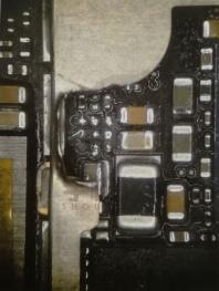
Checking the PCB bitmap, we know that PP1V8_GRAPE connects main touch screen chip U2401, main power supply U1202, touch control tube U2403 and part of resistors and capacitors, as shown in picture 4-88.
Picture 4-88


Many components are connected with PP1V8_GRAPE and it is not completely short circuit to ground. We cannot use the burn-in method either, so remove the relevant components one by one. The diode data does not change after removing the main touch screen chip U2401. Then remove the connected filtering capacitor and the data remains the same. Observing under microscope, we find that U2403 has been replaced by the last repairman. Use air hot gun to tear down U2403. Now measure the diode data to ground and it is normal. Tear down a touch control tube U2403 from a circuit board to assemble it and turn on iPhone to test. Trouble is removed.
Comments
Post a Comment