iPhone 6 Error 9 CPU Repair Without BGA Reball
Introduction
Have you ever come across with iPhone 6 error 9 issue? It is well known that once iPhone 6 error 9 appears while performing firmware update or system restores via iTunes, normal function becomes disrupted. And if this occurs frequently, that will be difficult to deal with. Several reasons are responsible towards the problem, and primary suspicion relates to the NAND Flash error as our previous blog has illustrated. This time we come up with a totally different solution regarding to iPhone 6 error 9 caused by insufficient soldering within CPU BGA.
Recommended Tools:
Maintenance Platform
Electron Microscope
Soldering Iron
Hot Air Gun
Stainless Steel BGA Scraper
PCB Holder
Anti-static Wrist Strap
Screw Drivers
LCD Opening Sucker
Tweezers (ESD – 11)
0.02mm Copper Wire
Metal Engraving Craft Knife
Steps
1. Phone Disassembling
The phone is stuck in Recovery Mode when trying to start up. Connect it with computer and start system restore via iTunes.
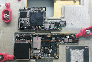
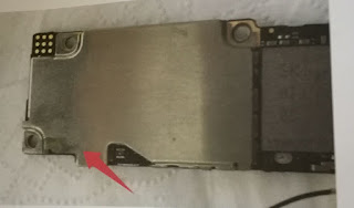
Error 9 appears. Disassemble the phone and take out the logic board. Remove a part of the shield plate with tweezers.
2. Malfunction Diagnosing
Test grounding resistance value of resistor R0317 and R0316 with diode mode-Abnormal value (480 under normal circumstances). R0317 and R0316 are connected with CPU pin AP31-SDA and pin AR31-SCL directly.
3. Malfunction Repairing
Take down the shield plate of CPU with hot air gun. Then put the logic board on the corresponding position of the CNC mold and fix it tightly. Load iPhone 6 corresponding logic board chip grinding program and start grinding.
Once finished, take out the logic board and use a engraving craft knife to scrape carefully until the CPU sub layer circuit comes out. After that, clean with PCB cleaner.
Apply some UV curable solder mask to the exposed area, apart from the two bonding pads (SDA,SCL). Once it has been done, put the logic board under the UV dryer lamp for 10 minutes and then take out the logic board.
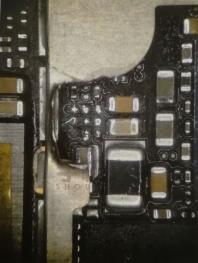
Solder tins on the two bonding pads with soldering iron. Then solder the 0.02mm copper wire to the two bonding pads respectively. The two soldered wires connect R0317-corresponding pad SDA and R0317-corresponding pad SCL respectively.
Test grounding resistance value of R0317, R0316 with diode mode again-Normal value this time.
4. Phone Testing
Assemble the phone and restore via iTunes. Then activate the phone and test, malfunction fixed.
Once test finished, take out the logic board. Then apply some UV curable solder mask to the soldered place again. Put the logic board under the UV dryer lamp for 10 minutes.
Assemble the phone and test again, all work normally.


Comments
Post a Comment