Troubleshoot:iPhone 6plus Boot not displayed
When Users are having trouble starting the iphone 6plus, as such the iPhone 6plus is able to boot and receive calls, but the screen does not display, we replaced the screen before opening it. It doesn't look much damage on the appearance, after replacing a new iPhone 6 Plus screen to test, it still doesn't display and no backlight.
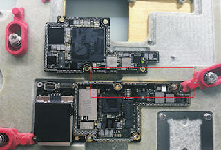
The measurement of display conncetion resistance is shown in picture 11-2-1.
The measured value is completely normal, there is no current burnt traces on the iPhone backlight chip and display power supply IC , so we can start to work on its display part. Taking off the display IC under good protection, and work on solder pad with low temperature solder, do not rush to replace the new IC, the bottom resistance should be measured before that. As shown in picture 11-2-2.
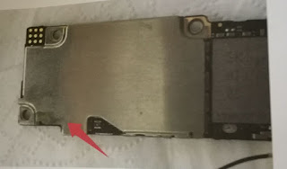
The result shows that the D3 pin I2C bus CPU has no resistance to the clock signal of the display power, and the C3 display has no resistance to the power IC signal. According to these two results, we can make sure that the lock screw is wrongly installed to cause the motherboard layer being broken. Open the 6P bottom screws column diagram,we find that C3 go through left and right sides of the screw column, D3 only go through the left, After removing the 2 screw columns, we find both of them get traces of damage (you can remove the screw columns with solder paste, hot air gun with 300 degrees and gently push then down by solder iron, we find there is serious disconnection on the left. As shown in picture 11-2-3.
First, scraping a waste main board without broken wire and observe the wire construction. Select a smaller phone fix scraper tool, gentlely scrape and try not to damage the bottom wire since there are several layers in the iPhone 6 plus motherboard. you need to pay attention if there is black layer shown up for sraping the first layer, then you can add a bit of soldering paste on it, it will be clear to see the specific location of the wire under a microscope.
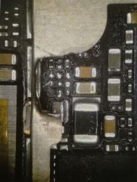
As shown in picture 11-2-4, we choose a similar sharp knife to throw off the location of the broken wire and find the thread. The left screw can find a resistance thread. We choose a sharp iron with professional jumpers to solder every wire carefully and try not to repair it next time.
We can solder the jumper under the microscope, as shown in picture 11-2-5, the screw column on both sides of the line have in common, the left one can not find the thread so we can use the right column to make jumpers, then we measure IC bottom pin resistance again. The resistance is normal, now solidifying with green oil and install display power supply to test.
Finally, the screen light and display normally again, functions are tested perfectly.


Comments
Post a Comment