iPhone 6 Touch Doesn’t Work Properly repair guide
The widespread use of mobile phones, the breakdown will be more and more, as follows to share some of the iphone phone failure repair experience. iPhone 6 touch is properly ineffective, when touch is not working, screen can display normally; the touch gets complete failure when there are some not obvious lines on screen. The device got water damage and screen was replaced, It's still not repaired well though repaired by another repairman.
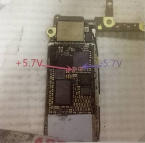
Tear down the iPhone 6 to check out, we find both black and white touch were replaced, some capacitance under audio IC get slight corrosion. First measure the positive and negative 5.7V power supply to the ground value, +5.7V positive measurement is 400+, - 5.7V negative measurement is 600+, both are normal as shown in picture 3-7-1.
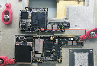
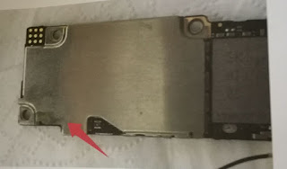
We did not find obvious problems after ground value measurement, in accordance with the exclusion method, we firstly replace black touch, test failure is same, then replace the white touch, test failure still exist. It means there is no problem on IC, and also no obvious problem we can find from the power value. Thus, the fault point should be on the display screen IC U1501 because it didn't apply the power supply, as shown in picture 3-7-2. Immediately remove the CPU shield to check U1501, we found the traces of welding which indicates last repairman is professional.
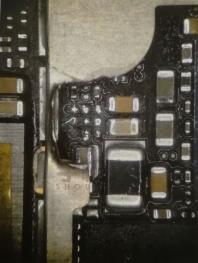
Remove the U1501 and check the solde pad, we can't find obvious corrosion and disconnection, as shown in picture 3-7-3.
Measure the U1501 pad to ground value by multemeter, -5.7V power supply output pin is normal 690+, +5.7V power supply output has no ground value, as shown in picture 3-7-4 and 3-7-5.
According to the backside +5.7V touch power supply has 400+ to the ground value as we tested, we can judge that the board is disconnected. As shown in picture 3-7-6.
Handle the pad with jumper wire (it's power supply here, output is recommended with amplifiers cable instead of headphones cable), and the pins(as shown in picture 3-7-7) on the IC are also need to be handled.
Sodering IC, measure booster ground value and +5.7V ground value with multemeter. As shown in picture 3-7-8, 3-7-9 and 3-7-10.
Booster and the touch +5.7V power supply to the ground value are normal, install screen to test, the touch can work normally as shown in picture 3-7-11.
Soldering jumper wire, cover it with brown adhesive tape, welding the shield cover,the iPhone 6 successfully repaired as shown in picture 3-7-12.
Schematic diagram for jumper wire as shown in picture 3-7-13.


if U1501 not generate voltage?
ReplyDelete